


Crystal Oscillator Application Test Report
1. Test Description:
Purpose: The customer reported that the board fails to keep time during product testing and requires a time reset on the following day. A total of 3 models of PCBA have been delivered to our company. We need to verify all parameters of the crystal oscillator circuit and issue a test report.
2. Individual Parameter and Application Circuit Test
1. Circuit Parameters:
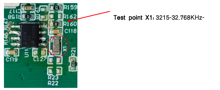
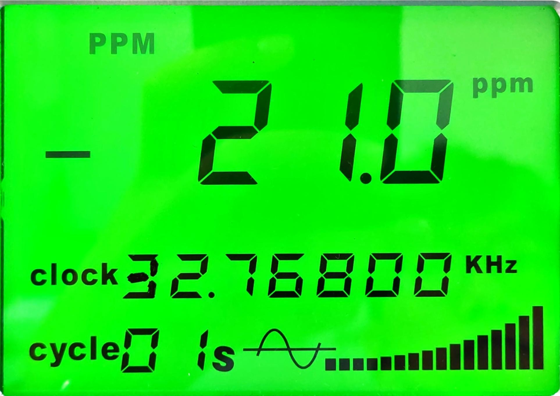
• Crystal Oscillator: 3215-32.768KHz-12.5pF
• DC Voltage: 5V
2. Circuit Board Diagram
3. Individual Crystal Oscillator Test
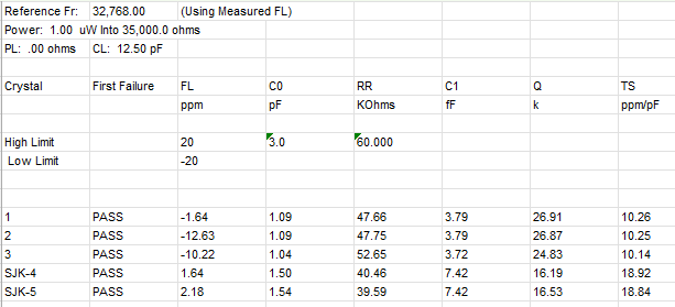
3.1 Test Data Comparison
Test was conducted on 3 pieces of crystal oscillators mounted on the respective PCBA boards, along with the backup samples (model: SJK3215-32.768KHz-12.5pF). The test data are as follows:
4. Application Circuit Test
4.1 v2.43
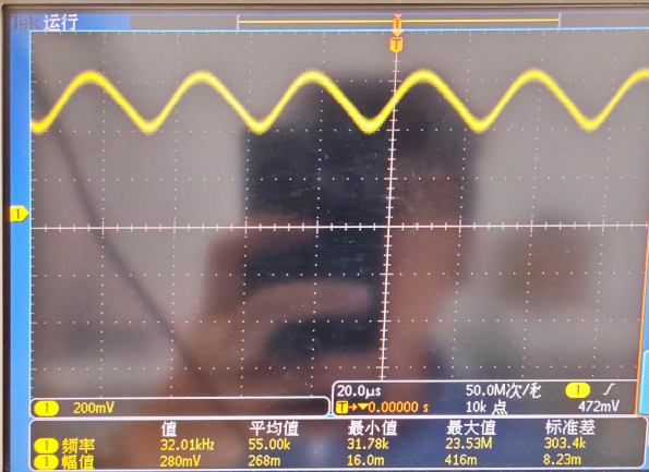
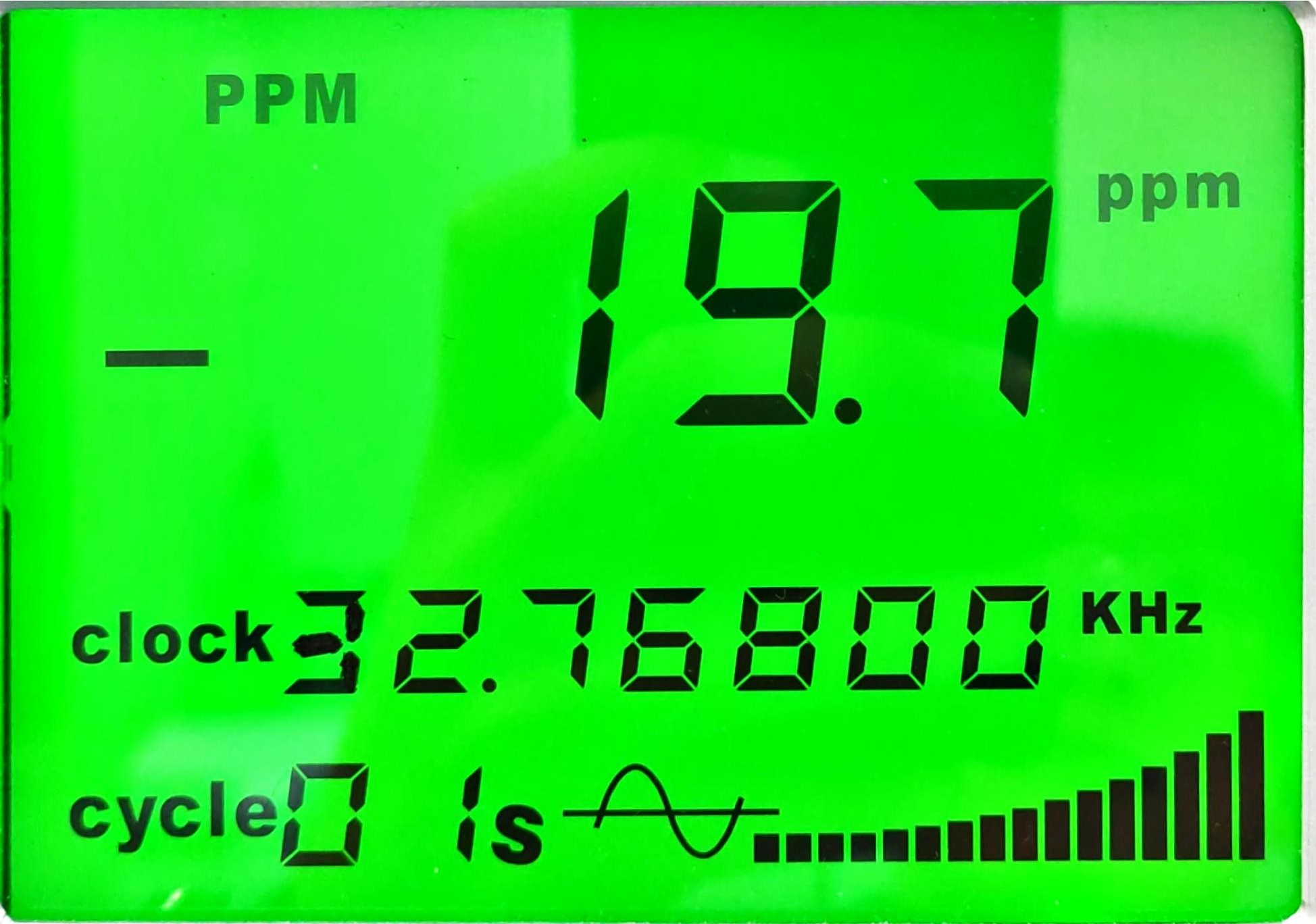
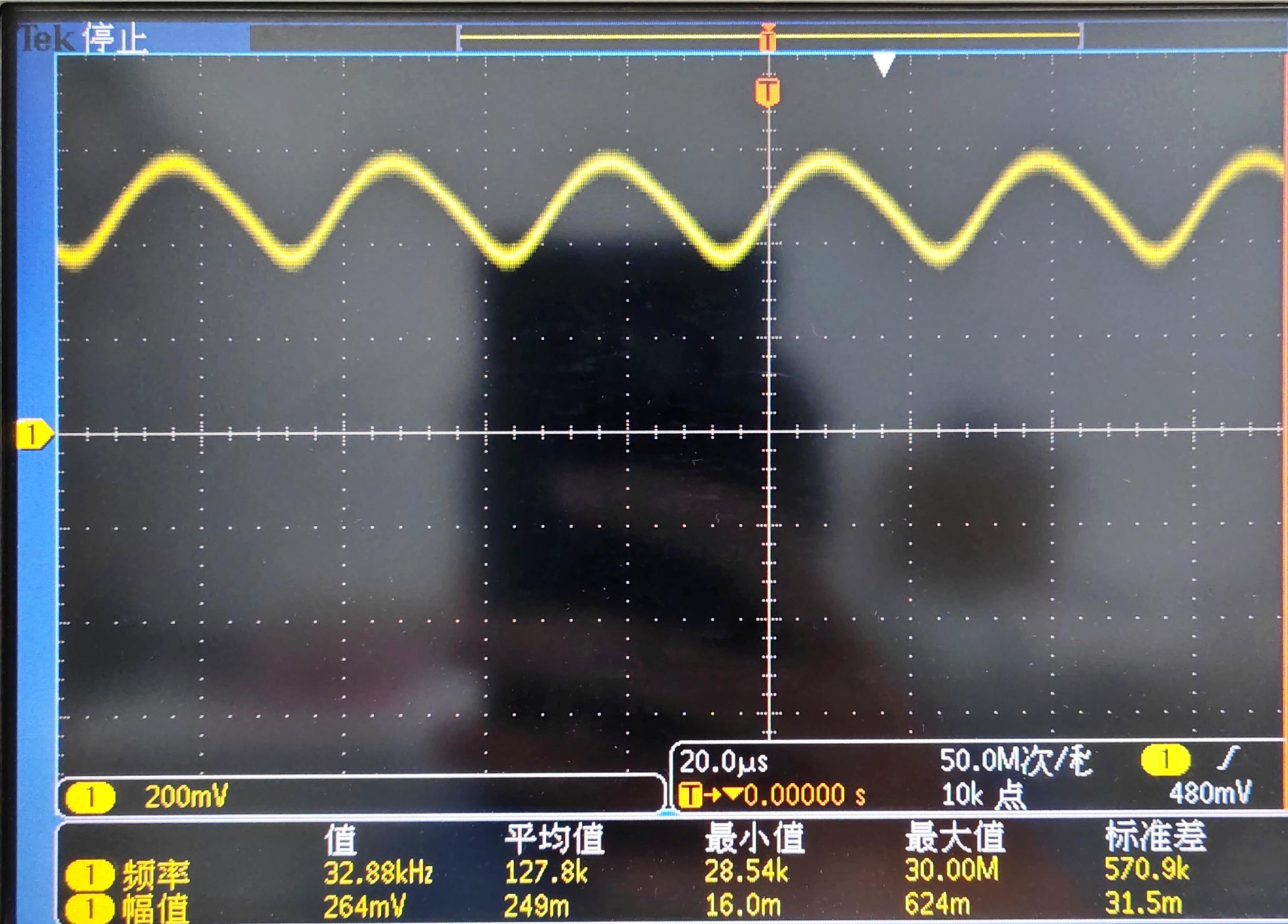
4.1.1 Test of the oscillation circuit for the 3215-32.768KHz-12.5pF crystal oscillator under the original board parameters is as follows:
 CLK-IN | 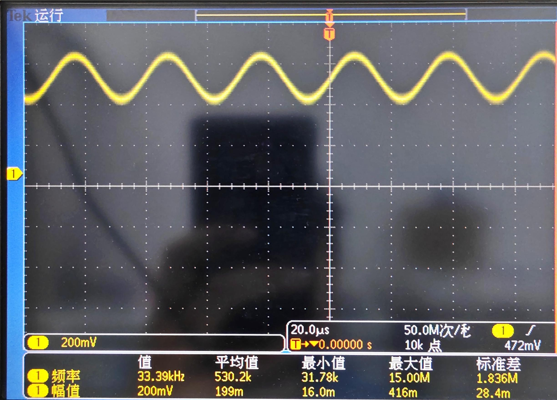 CLK-OUT |
Frequency:
Operating frequency of X1 oscillation circuit: FL=−19.7 ppm
(Reference value: ±20 ppm Max)
Series resistance margin of X1:
(Reference value: ∣−R∣>3 RR)
Result: NG
4.2 V2.52
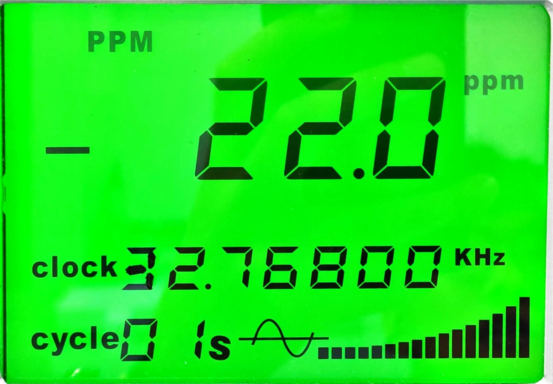
4.2.1 Test of the oscillation circuit for the 3215-32.768KHz-12.5pF crystal oscillator under the original board parameters is as follows:
 CLK-IN | 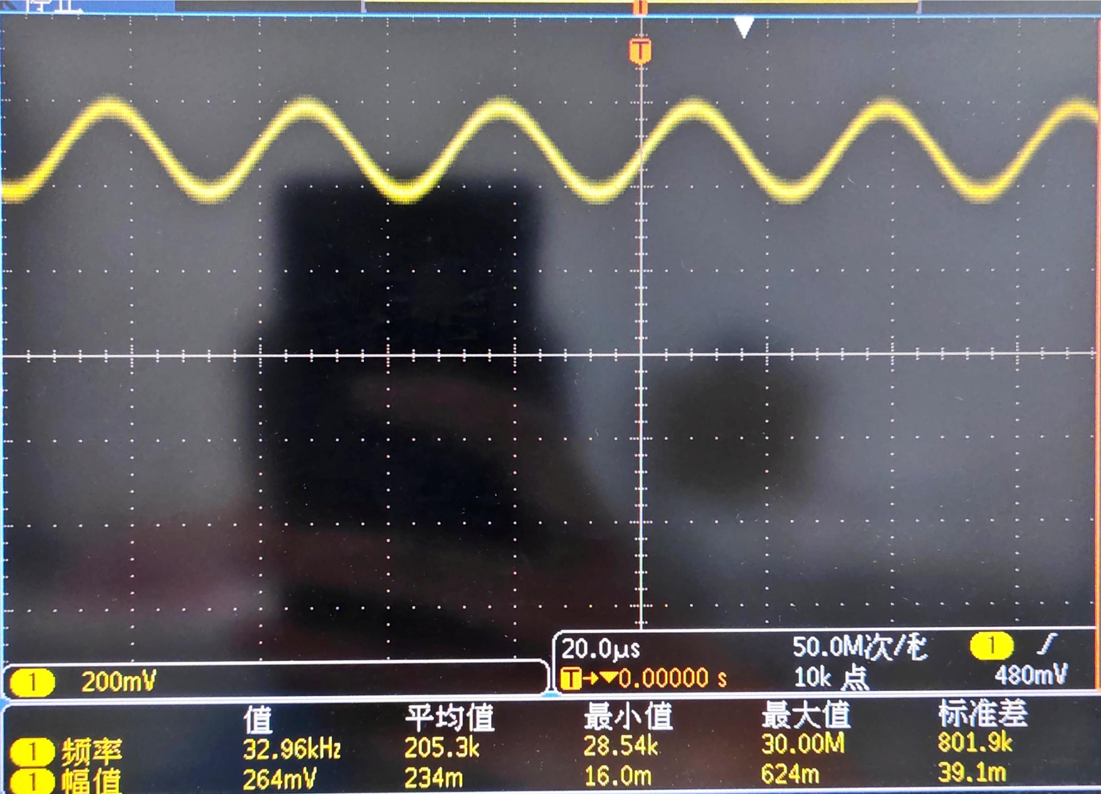 CLK-OUT |
Frequency :
Operating frequency of X1 oscillation circuit: FL=−22.0 ppm
(Reference value: ±20 ppm Max)
Series Resistance Margin:
Series resistance margin of X1:
(Reference value: ∣−R∣>3 RR)
Result: NG
4.3 V2.53
4.3.1 Test of the oscillation circuit for the 3215-32.768KHz-12.5pF crystal oscillator under the original board parameters is as follows:
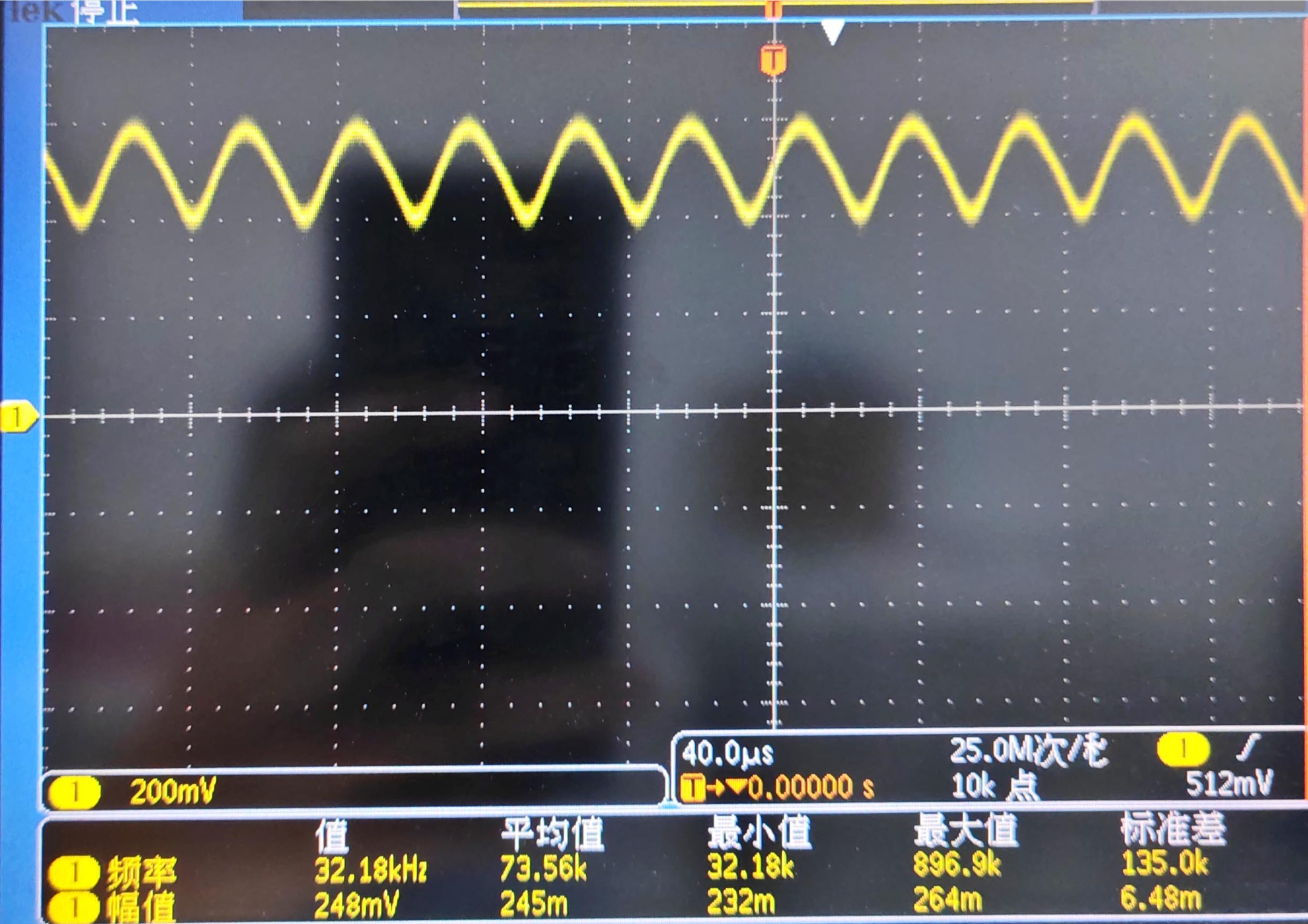 CLK-IN | 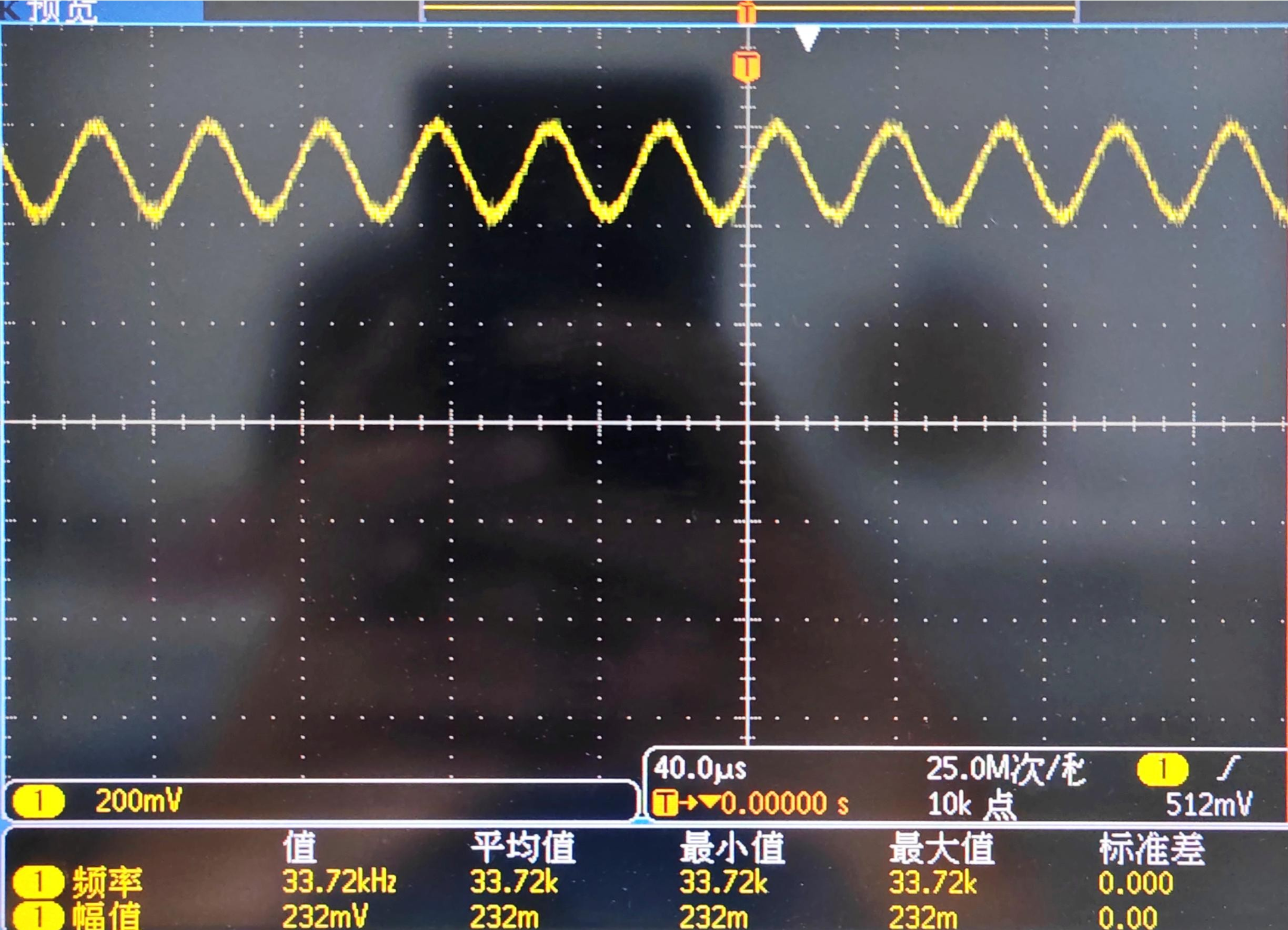 CLK-OUT |
Frequency :
Operating frequency of X1 oscillation circuit: FL=−21.0 ppm
(Reference value: ±20 ppm Max)
Series resistance margin of X1:
(Reference value: ∣−R∣>3 RR)
Result: NG
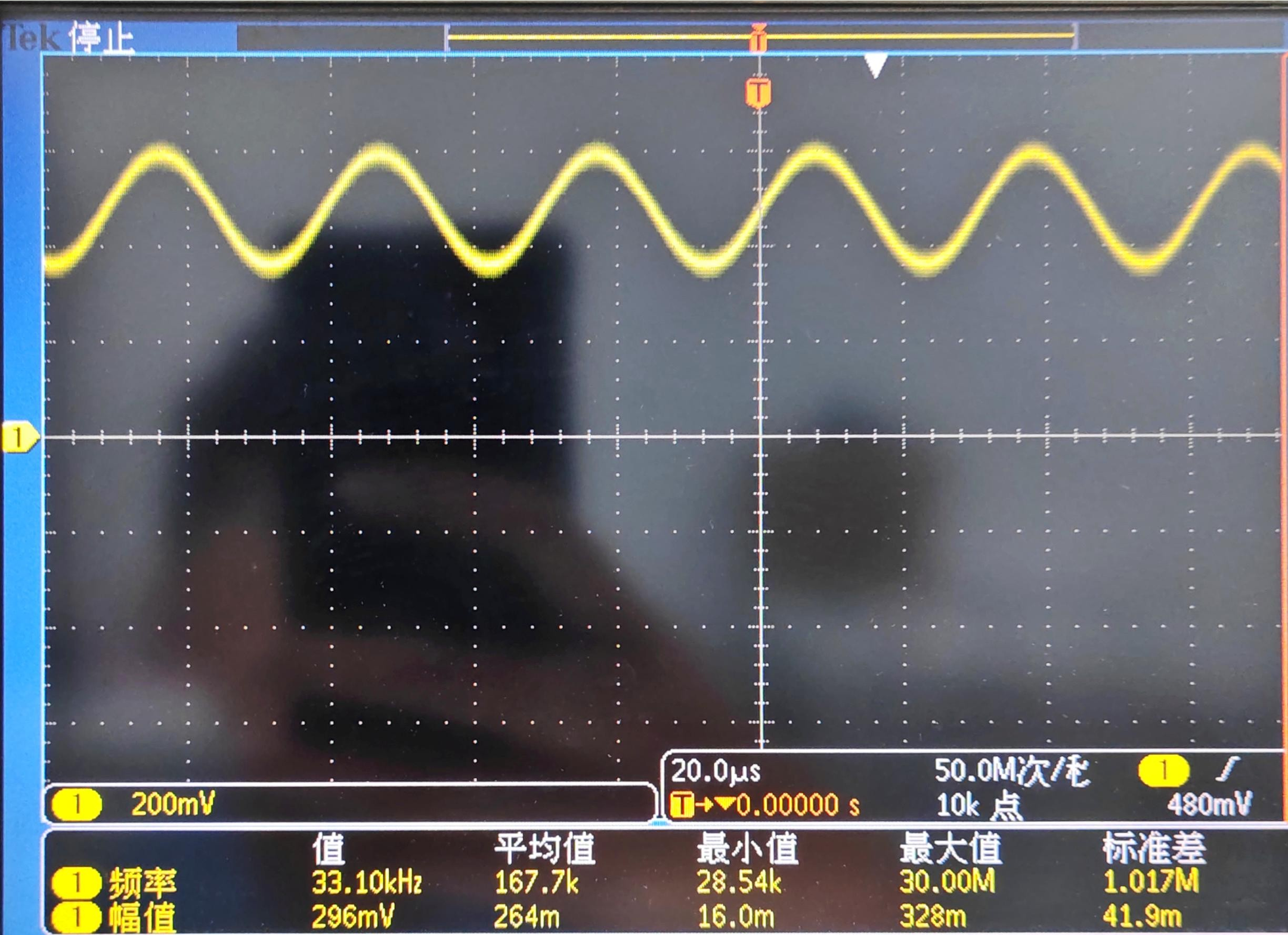 CLK-IN | 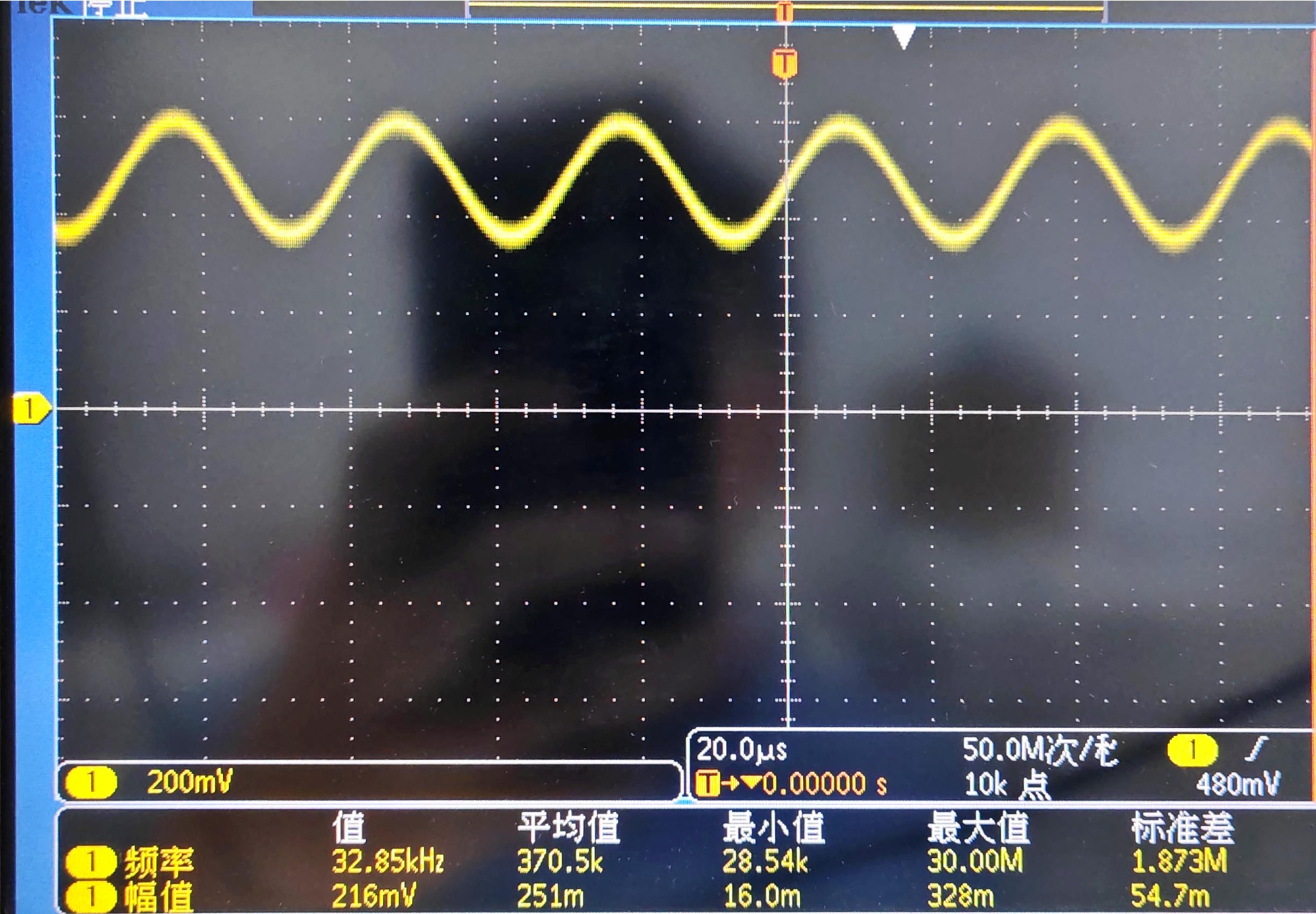 CLK-OUT |
Frequency :
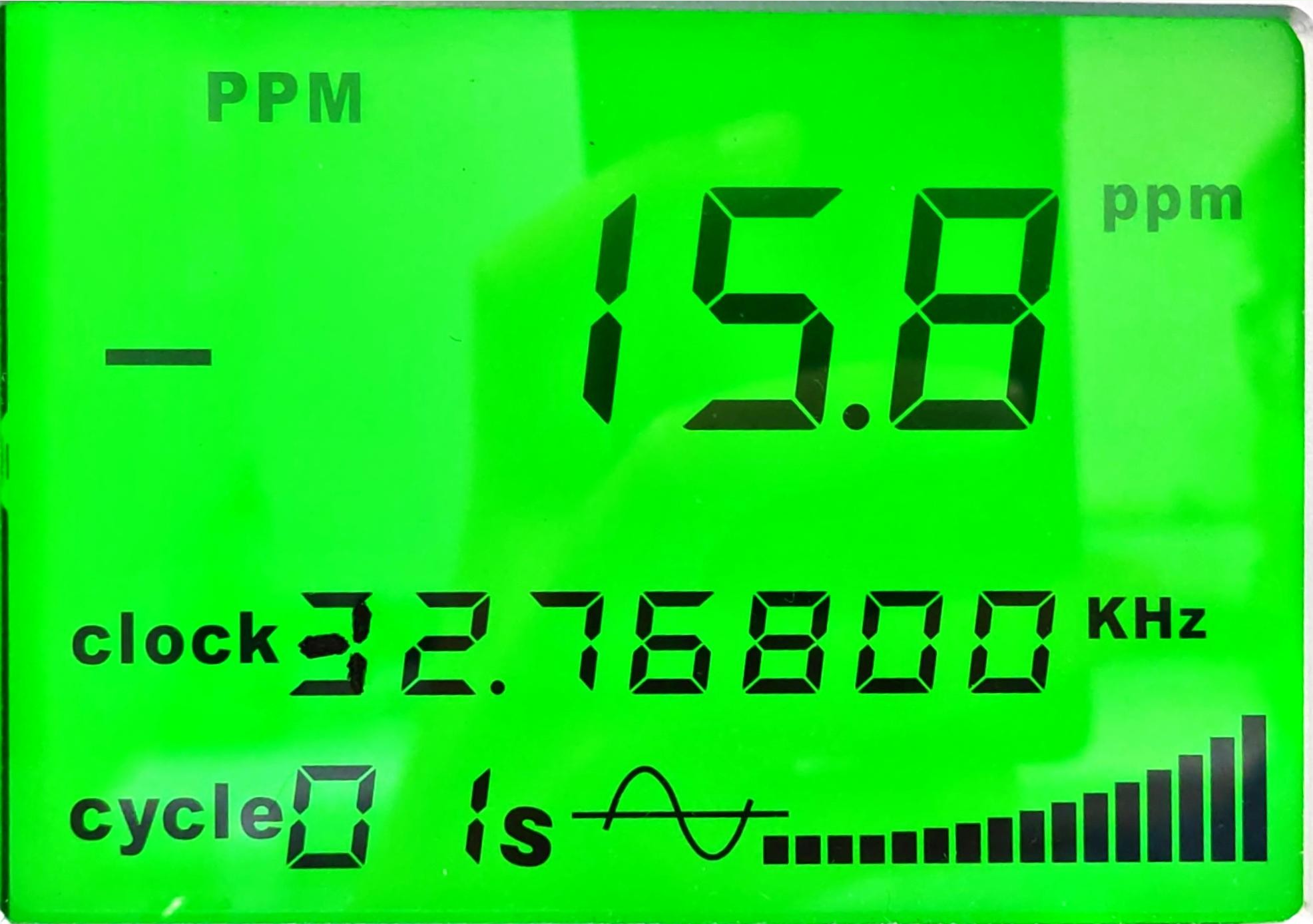
X1 Oscillation Circuit Operating Frequency FL = -15.8ppm (Reference Value ±20ppm Max)
X1 Series Resistance Margin |-R| > 50 KΩ (Reference Value |-R| > 3 RR) Result: NG
3. Overall Conclusion
Test Data:
| Project | Item/Type | F/on board(ppm) | Series Resistance Margin(KΩ) | Conclusion |
| V2.43 X1 | 3215-32.768KHz-12.5pF | -19.7 | >40 | -R NG |
| SJK-3215-32.768KHz-12.5pF | -15.8 | >50 | -R NG | |
| V2.52 | 3215-32.768KHz-12.5pF | -22.0 | >40 | -R NG |
| V2.53 | 3215-32.768KHz-12.5pF | -21.0 | >40 | -R NG |
Test Results:
As can be seen from the above test results, the crystal oscillation stop phenomenon described by your company should be caused by insufficient series resistance margin of the crystal circuit, with the root cause being a mismatch between the IC and the crystal.
In reference to the specifications of ISL1208, we recommend that your company choose one of the following two options for improvement attempts:
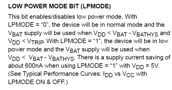
1、The ISL1208 specification mentions that this IC has a power-saving mode. It is recommended to disable the power-saving mode and then use the SJK-3215-32.768KHz-12.5pF crystal with lower resistance to provide more series resistance margin. The specific description is as follows:
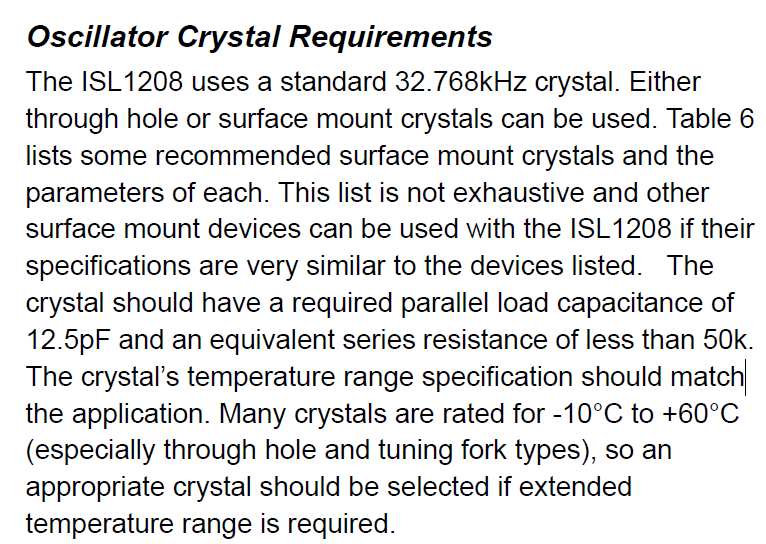
2、The ISL1208 specification indicates that this IC is only compatible with crystals with a motional resistance value below 50KΩ. However, the measured motional resistance value of the crystal on the PCBA provided by your company either exceeds 50KΩ or is at the threshold. It is recommended that your company adopt our 32.768KHz crystal with a lower motional resistance value.

Contact
Official Chinese website:www.q-crystal.com.cn
Satisfaction quality, Just-in-time service, and Key-cost offering
©2026 SJK All Rights Reserved.